


Design and analysis of hydraulic drive system for monorail Crane
Li Kunquan, Wen Jian
(Henan Institute of Engineering, Zhengzhou 451191, China)
Abstract: A set of hydraulic drive device was designed for the mine monorail crane. The Solidworks modeling software is used to establish the 3D model of the driving mechanism. The stress state of the driving wheel is analyzed, the hydraulic driving circuit is designed, and the driving principle is expounded. The hydraulic modeling software AMESim is used to establish the simplified hydraulic circuit, and the main parameters are set according to the actual working conditions. The mass displacement curve, the motor speed and output torque change curve and the oil pressure change curve in the pump are obtained. The results show that the loop response time is 0.7S, the motor stable running speed is 82r/min, the output torque and the oil pressure in the pump all meet the basic requirements of the monorail crane with the driving force of 20kN.
Key words: monorail crane; Hydraulic system; Driving device; AMESim;
0 Introduction
As a kind of underground auxiliary transportation equipment, monorail crane has obvious advantages in performance. As the walking part of monorail crane, the driving part has great influence on the production and production efficiency of coal mine. Because the walking track of the monorail crane is suspended and fixed at the top of the roadway, it is different from the traditional power trolley and the special working environment in the coal mine, the design of its driving part is more limited. The hydraulic motor is used to provide torque to the driving wheel perpendicular to the track web of the I-beam, and forward force is generated by friction, which is a relatively mature driving technology of monorail crane at present.
1. Drive mechanism model
The driving unit provides the driving power and braking force of the monorail crane. The three-dimensional model of the driving mechanism is shown in Figure 1. The driving wheel and the hydraulic motor constitute the driving mechanism, and the pressure spring presses the pair of driving wheels on the web through the connecting rod mechanism, and the hydraulic motor provides the torque required by the monorail crane. When the monorail crane needs to brake, the brake spring extends to drive the arch brake plate to rotate, the brake block and the web contact friction, generating braking force.
In a single monorail crane, the driving unit can be installed in 1 or more groups according to the actual load, but the design principle of the hydraulic system is the same. A monorail crane equipped with two groups of driving units is arranged by installing the driving units in series in Figure

Figure 1. 3D model of driving mechanism
1. I-beam 2. Drive wheel 3. Hydraulic motor 4. Fixed plate 5. Pin shaft 6. Bow brake plate 7. Brake spring
2. Driving principle analysis
2.1 Force analysis of driving wheel
The driving wheel has a complex force on the track. The driving wheel rotates under the rotational torque M0 provided by the driving motor, and is subjected to the positive pressure Fn from the pressure spring, and then subjected to the friction Fu and supporting force Fn under the action of the track, the rolling friction resistance couple Mm0 and the driving force of the monorail are evenly divided into the resistance Fzu of a single driving wheel. The force diagram of the driving wheel is shown in Figure
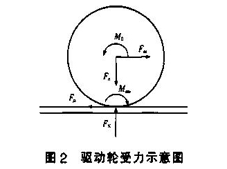
From the equilibrium conditions of the force on the object
M ○ >M^+Fm-r 1
M^Fn-a 2
In the formula, the radius of r driving wheel is set as r=150 mm; a - Rolling friction factor,a=2.0. When the monorail crane runs smoothly, the speed is set at 1.0m /s, and the positive pressure FN= 15kN; The driving force of monorail crane is 20 kN, 2 groups of driving devices, 4 driving wheels, Fzu=5kN. The relationship between driving wheel radius and motor parameters is shown in Table 1。
2.2 Principle analysis of hydraulic system
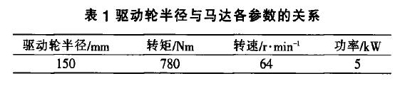
The number of motors in hydraulic system is different, requiring good synchronization of motors. Due to the slope of the track, in order to control the speed of the monorail crane within the allowable range, the hydraulic circuit requires a certain balance; The overall mass of monorail crane is larger, and the buffer performance of the loop is strictly required when starting and braking. The schematic diagram of the hydraulic drive system is shown in Figure 3.

FIG. 3 Schematic diagram of hydraulic drive system
1, 6. Externally controlled balancing valve (composed of two-way balancing valve) 2, 5. Externally controlled one-way throttle valve (composed of two-way throttle valve) 3. Filling valve group 4. Buffer valve group 7. Three-position four-way reversing valve 8. Pump A, B. Symmetrical oil circuit a, b. Motor group
(1) Motor positive and negative loop monorail crane starts, pump 8 oil supply high pressure oil through reversing valve 7(spool in the left position), flow through the balance in turn
Valve 6 and unidirectional throttle valve 5(while the high pressure oil passes through the left oil circuit B in the same way), motor group a starts running; At the same time, the high pressure oil provided by pump 8 makes the throttle valve 2 and the balance valve 1 in the open state, and the low pressure oil flowing out of the motor goes back to the tank through the reversing valve 7. If the spool of reversing valve 7 reverses to the right, the motor reverses and the monorail crane runs in reverse. Four motors are connected in parallel, and the same group of motors are installed on both sides of the track in parallel, with the same load and motor synchronization.
(2) Balance loop when the monorail crane speed is too large, the pump 8 oil supply pressure drops (with the motor is turned into an example), the externally controlled throttle valve 2 throttle port is reduced, the balance valve 1 is blocked, the motor speed is reduced, play a balancing role; At the same time, the oil supply pressure begins to increase, first open the balance valve 1, the throttle valve port of the throttle valve 2 gradually increases until the oil pressure reaches balance. The overall mass of the buffer loop monorail crane is large, and the hydraulic vibration impact caused by its sudden start, stop or turn is very large. The buffer valve group 4 consists of a responsive small direct acting relief valve and 4 check valves. When the hydraulic impact occurs, the pressure on the return or inlet side surges, exceeding the pressure set by the relief valve. The relief valve opens the overflow to buffer the hydraulic impact; At the same time through the check valve to the other side of the oil.
3. System and result analysis
3.1 AMESim model establishment and parameter setting
According to the actual working conditions and the principles mentioned above, the hydraulic drive system model of monorail crane is established according to the actual structure of hydraulic components, as shown in Figure 4. In the modeling process, unidirectional throttle 2 is constructed by the module of HCD library, and the rest components are selected from Mechani-cal and Hydraulic libraries. In order to improve the calculation efficiency of the model, on the basis of not affecting the system characteristics, the supplement valve group 3, the reversing valve 7, the relief valve and one symmetrical oil circuit are simplified.
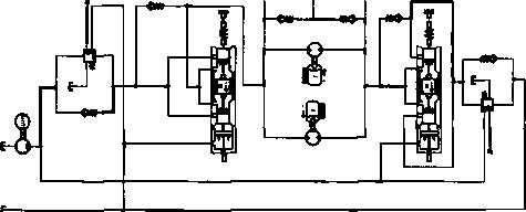
FIG. 4 AMESim model of hydraulic drive system
In the setting of component parameters, the angular displacement signal in the actual process is replaced by the linear displacement signal of the brake according to the actual operating condition of the monorail and in order to ensure the operational efficiency. The influence of pipeline length, resistance and liquid compressibility in the hydraulic system is ignored. Set the time to 10 seconds and the communication interval to 0.1s. The main parameters of the whole model element: motor speed /r-mirT1 1 500 pump rated capacity /mL-r-1
One-way throttle model mass block /kg 2.0 one-way throttle model spring stiffness /N.m-i 10000 motor viscous friction factor 12
Motor displacement /mL-r1 200 hydraulic oil power viscosity /nm^s-1 0.025 Buffer valve set relief valve pressure /MPa 0.5 Balance valve set relief valve pressure /MPa 3.5
3.2 Result Analysis
(1) The displacement change curve of the mass block of the unidirectional throttle valve model in the process of 10 s is shown in Figure 5. It can be seen that in the process of 0~5.0s, the mass block vibrates in a certain amplitude, the maximum value is 0.13m and the amplitude decreases gradually. After 5.0s, the mass block tends to be stable. This shows that using HCD to build the throttle valve model to establish the correct model foundation is feasible.
4 Conclusion
(1) The U hydraulic motor provides torque for the driving wheel to walk on the web of the I-beam. The driving part is independent of the frame, easy to install and the number can be designed according to the load.
(2) The motors are distributed in pairs on both sides of the track web. For the hydraulic system, the positive and negative circuit, balance circuit and buffer circuit of the motor are mainly considered. For the monorail crane with more than one group of driving parts, its hydraulic circuits can be connected in parallel.
(3) The driving force of the monorail crane is 20 kN, 2 groups of driving devices, the motor speed is 1500r/min, the rated displacement of the pump is 400 mL/r; The motor response time is 0.7s, the speed is 80 r/min, and the output torque is 1.0kNm, which is basically consistent with the theoretical value.
References:
[1] ZHU Tianlong, Design of Electro-hydraulic Control System for Cable Bearing Vehicle Group [J]. Coal Technology,2017,36(7):304-306.
[2] Chen Kaixuan, Zhang Lixiang, Ye Liang, Structural Optimization of the Travelling Device of the Infinite Rope Monorail [J]. Coal Technology, 2016,35(10):282-284.
[3] LU Yongxiang, Hydraulic Pneumatic Technical Manual [K]. Beijing: China Machine Industry, 2007.C4J ZHAO Jing, KOU Ziming, FAN Peng, et al. Research on Hydraulic System of Belt Conveyor Belt Changing Device Based on AMESim [J]. Chinese Hydraulics & Pneumatics,2014(12):91-95,99.
[5] TU Yongping, Performance Analysis of Hydraulic System of Hydraulic Support Based on AMESim [D]. Chongqing: Chongqing Jiaotong University, 2014.
[6] LI Rui, HOU Youfu, Improved Design of Mineral Emulsion Chestnut [J]. Chinese Hydraulics & Pneumatics, 2012(7):114-115.t7j GUO Zehai, HOU Hongwei Fuyang. Analysis of Brake Connecting Rod of Monorail Crane Brake Device [J]. Coal Mine Machinery, 2015,36(11) :188-89.
[8] Guo Zehai, Hou Hongwei, Fu Yang. Design and Analysis of New Driving Part Based on Monorail Crane [J]. Coal Mine Machinery, 2016,37(1>:144-145.
| Previous:Working principle of micron level dry fog dust suppression | Next:Working principle of micron level dry fog dust suppression |

 TEL
TEL
 PRODUCTS
 SOLUTION
 CONTACT